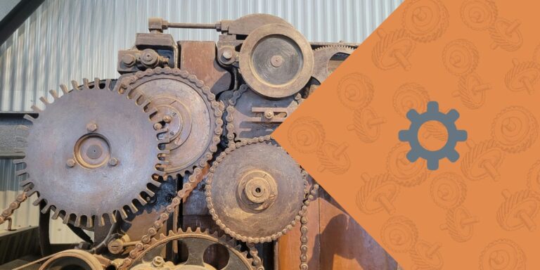
What is a Reverted Gear Train?
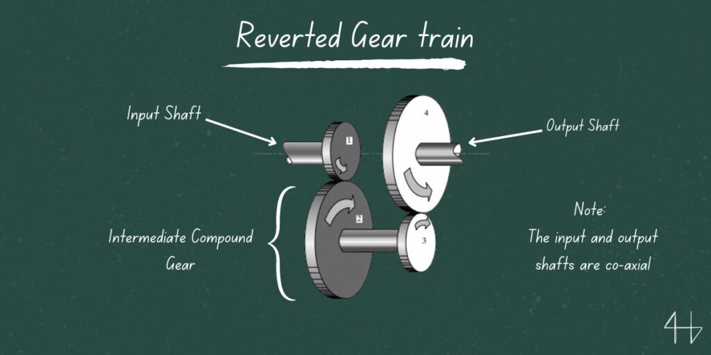
A reverted gear train is a type of compound gear train with a specific configuration of gears where the input and output shafts are collinear, meaning they share the same axis.
This arrangement is designed to achieve a specific gear ratio in a compact space while ensuring the input and output shafts remain aligned along the same axis.
Characteristics of a Reverted Gear Train
Collinear Input and Output Shafts: The most distinctive feature of a reverted gear train is that the input and output shafts are in line with each other.
Equal Center Distance: The distance between the centers of the first and second gears is equal to the distance between the centers of the third and fourth gears. This ensures that the gears fit within a confined space and maintain alignment.
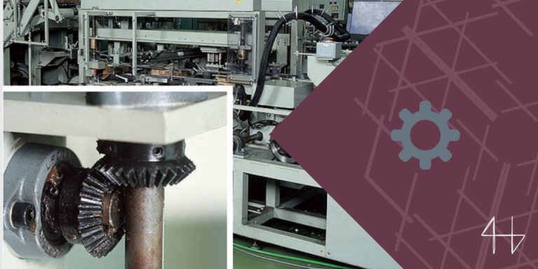
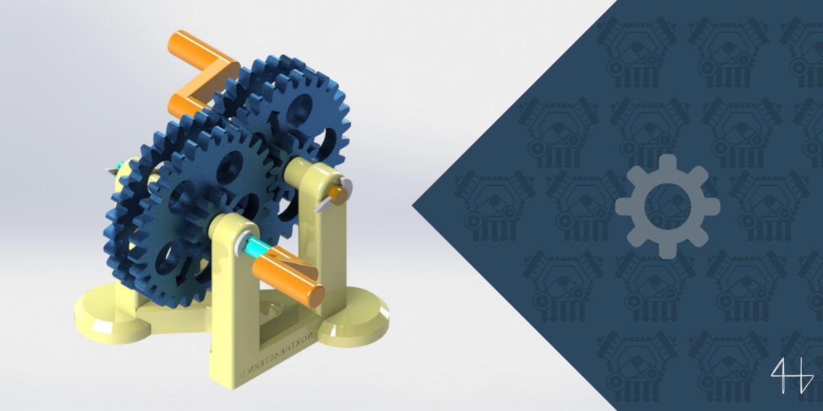
Four-Gear System: Typically, a reverted gear train consists of four gears. The gears are arranged in such a way that the first gear (on the input shaft) meshes with the second gear. The second gear is mounted on the same shaft as the third gear, which in turn meshes with the fourth gear (on the output shaft).
Identifying a Reverted Gear Train
Check Shaft Alignment: Verify that the input and output shafts are aligned on the same axis.
Count the Gears: Ensure there are four gears in the system, with the specific meshing pattern where gears 1 and 2 mesh gears 3 and 4 mesh, and gears 2 and 3 are mounted on the same intermediate shaft.
Measure Center Distances: Measure the distance between the centers of the meshing gears. The distance between the centers of gears 1 and 2 should be equal to the distance between the centers of gears 3 and 4.
Working principle of a Reverted Gear Train
A reverted gear train is a specific type of gear mechanism where the input and output shafts are aligned, but the gears are arranged in such a way that the direction of rotation and the gear ratio are carefully managed.
Here’s a breakdown of how it works:
1. Gear Arrangement: In a reverted gear train, the gears are arranged such that the input gear (driving gear) and the output gear (driven gear) are on parallel shafts. This means the shafts are coaxial or in the same plane, making the train’s layout compact.
2. Gear Ratios: The reverted gear train uses a series of gears to achieve a desired speed reduction or increase. The gear ratio is determined by the number of teeth on each gear in the train. For instance, if you have three gears in a row, the gear ratio will be the product of the ratios between the gears.
3. Gear Direction and Reversal: One characteristic of a reverted gear train is that the rotation direction of the output gear relative to the input gear can be controlled. Typically, an odd number of gears between the input and output shafts results in a change in the rotational direction (each intermediate gear reverses the direction once), while an even number results in the same direction.
4. Mechanical Efficiency: The reverted gear train can be designed to provide a high level of mechanical efficiency and torque transmission. By carefully selecting gear sizes and configurations, engineers can optimize the train for specific applications.
A reverted gear train is designed to align the input and output shafts while managing rotation direction and gear ratio through a specific arrangement of gears between the input and output gears.
It’s often used in applications where space constraints require the input and output shafts to be aligned, such as in some types of machinery and automotive transmissions.
Advantages vs Disadvantages of a Reverted Gear Train
When evaluating a reverted gear train, it’s important to weigh both the pros and cons. Consider how the respective gear placement, gear reduction ratio, and driven gear position influence performance. Below are the key advantages and disadvantages to consider.
Advantages
Disadvantages
Where to find Reverted Gear Train?
Understanding where reverted gear trains are commonly used can help you appreciate their role in mechanical systems.
These gear trains are particularly useful when you need the input and output shafts to rotate at the same speed but in opposite directions. You’ll often see them in applications requiring a precise speed ratio between two or more gears.
So, where exactly can you find reverted gear trains in action?
Here are some common places:
Elevators
In elevators, maintaining precise speed ratios is crucial for smooth operation.
Typically, two gears handle the main drive, while intermediate gears adjust the motion between them.
This setup ensures the elevator moves at a controlled speed, providing safety and comfort for passengers as it ascends and descends.
Washing Machines
Washing machines rely on different gear ratios to switch between washing and spinning cycles.
An intermediate gear connects the motor and drum, creating a simple gear train that adjusts the speed and torque. This efficient system ensures smooth transitions between tasks while maximizing performance.
Aircraft Mechanisms
Aircraft mechanisms rely heavily on complex gear systems to control flight surfaces, landing gear, and engine components.
These mechanisms ensure precise movements, stability, and safety during operation. From controlling wing flaps to retracting landing gear, the reliability of aircraft depends on well-designed gear mechanisms.
Key Considerations For Successfully Designing a Reverted Gear Train
Designing a reverted gear train requires careful attention to several critical factors.
This type of gear train is often used when you need to transmit power between two shafts that are close together. However, it’s not just about space.
Ensuring that the system efficiently converts rotational motion while maintaining precise rotational speeds is key to a successful design.
Wrapping up
A reverted gear train is a compact and efficient mechanism used to transmit power between closely positioned shafts.
To design one successfully, you must consider factors like space constraints, the need for precise rotational speeds, and the efficient conversion of rotational motion.
By focusing on these key elements, you can ensure that the gear train operates smoothly and meets performance requirements.
Project: Build your own reverted gear train.
FAQs about Reverted Gear Train

What is the speed ratio of a reverted gear train?
The speed ratio of a reverted gear train is determined by the ratio of the teeth on the driver and driven gears.
It’s calculated as the product of individual gear ratios, typically ensuring input and output shafts rotate at desired speeds.
What is a reverted gear train back gear in a lathe?
A reverted gear train back gear in a lathe allows for lower spindle speeds while maintaining torque.
It enables precise cutting at slower speeds, which is essential for machining tough materials or performing intricate operations.
Can a reverted gear train change output direction?
Yes, a reverted gear train can change the output direction.
By carefully configuring the gears, the system can reverse the direction of rotational motion, depending on the arrangement and interaction of the gear pairs.