The concept of gears is ancient. They were invented in the 3rd century BC. That is a long time for people to experiment and come of with different types of gear that would suit their needs best.
Understanding the types of gears and their uses can simplify your choices when it comes to power transfer, speed control, and torque adjustment in machinery. This article offers gear types explained with examples of gears in action, making it easy to pick the right one for any application.
Spur Gears
Basics
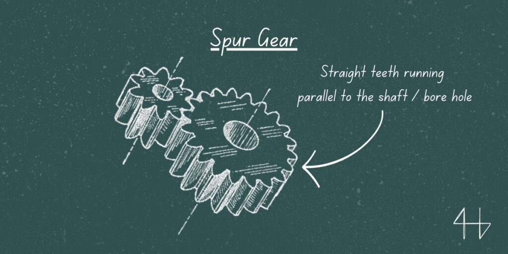
Spur gears are the most common type, featuring straight teeth and designed for simple, efficient power transmission between parallel shafts. They offer high reliability and are cost-effective. Ideal for low-speed applications, spur gears are widely used in conveyors and simple machinery.
Practical Application Examples
- Automotive transmissions
- Industrial machinery
- Conveyor belts
- Washing machines
Working Principle
A spur gear is a cylindrical gear with straight teeth cut parallel to the axis of rotation, used to transmit power and motion between parallel shafts. Spur gears are placed together so that the teeth of the gears mesh together in the gear train.
This is done so that when the one gear rotates, the teeth will push on the teeth of the other gear that it is meshed together with to create a transfer of rotational power.
Helical Gears
Basics
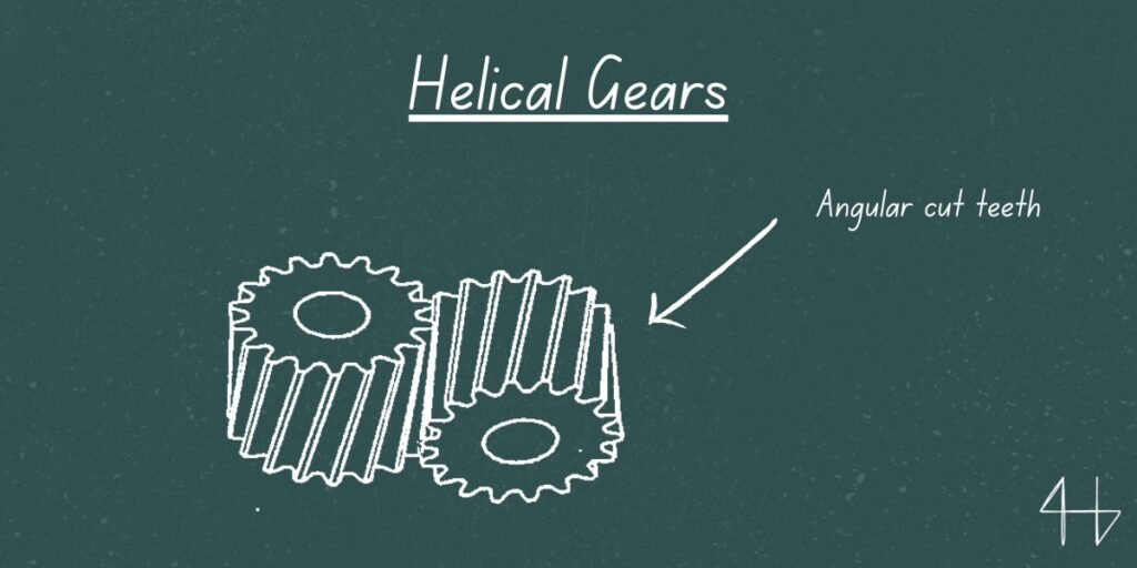
Helical gears have angled teeth, providing smoother and quieter operation compared to spur gears. They handle higher loads and speeds effectively, making them suitable for applications like car transmissions and industrial equipment.
The angled teeth engage gradually, reducing noise and wear.
Practical Application Examples
- Automotive transmissions
- Industrial gearboxes
- Robotics
Working Principle
The working principle of helical gears is very similar to spur gears. Helical gears are placed together so that the teeth of the gears mesh together in the gear train.
This is done so that when the one gear rotates, the teeth will push on the teeth of the other gear that it is meshed together with to create a transfer of rotational power.
Because their teeth are cut at an angle, they have less backlash, which means that they minimize their impact forces and reduce noise.
Gear Racks (Rack and Pinion)
Basics
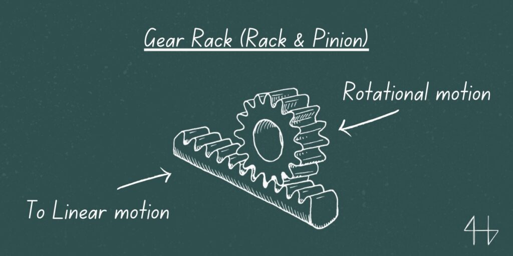
A gear rack is a straight bar with teeth that meshes with a round gear (pinion) to convert rotational motion into linear motion. It’s often used in rack-and-pinion steering systems and lifting devices.
This setup allows precise control over movement and positioning.
Practical Application Examples
- Lifting mechanisms (Forklifts and cranes)
- Car seat adjustments
- Garage door openers
- Electric gates
Working Principle
The working principle of gear racks is simple but effective.
When the pinion gear rotates its teeth mesh with the teeth on the rack and the rack moves linearly. This linear motion is directly proportional to the circumference of the pinion’s pitch circle.
In applications where a longer length than a single gear rack is required multiple racks can be joined together.
These racks often have tapping mounting holes to secure them in place.
For shorter applications gear racks are also available in specific lengths to give design and functionality flexibility. If the rack is fixed and the pinion is rotated the pinion itself will travel along the length of the rack and give a reliable solution for converting rotary motion to precise linear movement.
Bevel Gears
Basics
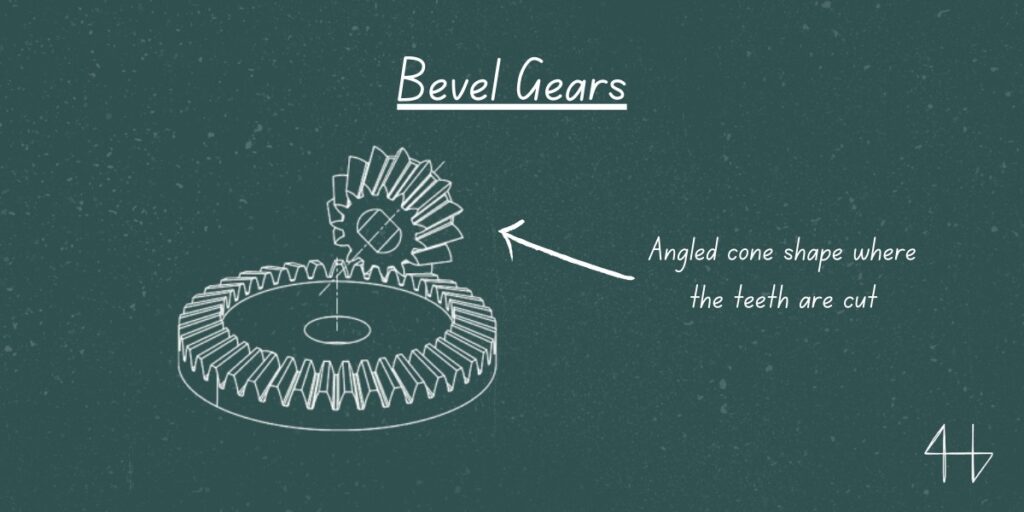
Bevel gears have cone-shaped surfaces and teeth that enable power transfer between intersecting shafts, usually at a 90-degree angle. They are perfect for applications like drills and differential drives. This design allows efficient speed and torque conversion in compact spaces.
Practical Application Examples
- Helicopter rotors
- Steering systems
- Printing presses
Working Principle
Simply put, bevel gears change the direction of force between two shafts.
Less simply put, bevel gears work by meshing a bevel pinion with a larger bevel gear. As the pinion rotates the tooth line of the pinion engages with the corresponding teeth on the bevel gear. This transfers torque and changes the direction of rotation.
The pitch angles of both gears must be matched exactly for smooth operation.
The mounting distance between the gears is also critical for alignment which is essential for optimal performance and to get the mechanical advantage you want. Kinda pointless if the distance between two gears is so large they don’t touch, so be careful.
Miter Gears
Basics
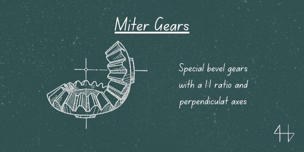
Miter gears are a specific type of bevel gear, designed to transfer motion at a 90-degree angle but with a 1:1 speed ratio. They are ideal for applications needing a simple right-angle power transfer without speed change, such as in hand drills.
Practical Application Examples
- Helicopter rotors
- Robotics
- Printing presses
Working Principle
Miter gears work by connecting two shafts at a 90-degree angle, allowing one to drive the other.
As one gear spins, it transfers motion to the second gear, which moves in the opposite direction at the same speed.
The conical shape of the gears ensures smooth power transfer, making them efficient for machines like drills or engines.
Worm Gears
Basics
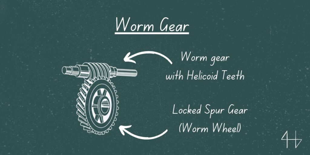
Worm gears consist of a screw-like worm that meshes with a gear, creating high torque reduction with minimal space.
They’re commonly used in heavy equipment and conveyor systems, where compact, smooth operation is essential. Worm gears also offer a self-locking feature, preventing back-driving.
Practical Application Examples
- Lifts / Elevators
- Turning instruments
- Cranes
- Hoists
- Mining machinery
- Automatic gates and conveyors
Working Principle
Screw Gears
Basics
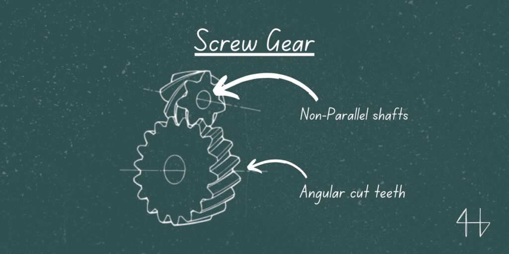
Screw gears, or crossed helical gears, are designed for non-parallel, non-intersecting shafts. They transfer power efficiently at angles and provide quiet operation. They’re often used in small mechanical devices where compact design is important.
Practical Application Examples
- Robotics
- Precision machinery
- Automotive steering systems
- Aerospace control systems
Working Principle
Screw gears work by meshing their helical teeth, which meet at a specific contact point to transfer motion and torque between shafts.
The helix angle, which is the angle at which the teeth are cut relative to the gear axis, plays a crucial role in this process. The direction of rotation and whether the gears are of the same or opposite hand (right or left) affects how the gears transmit motion.
If both gears have the same helix direction, they are suited for transmitting motion between skewed shafts.
However, using screw gears with opposite-handed helices allows for power transfer between parallel shafts. This unique capability to connect both parallel and non-parallel shafts makes screw gears versatile in machinery where space constraints or unusual layouts are a factor.
Internal Gears (Ring Gears)
Basics
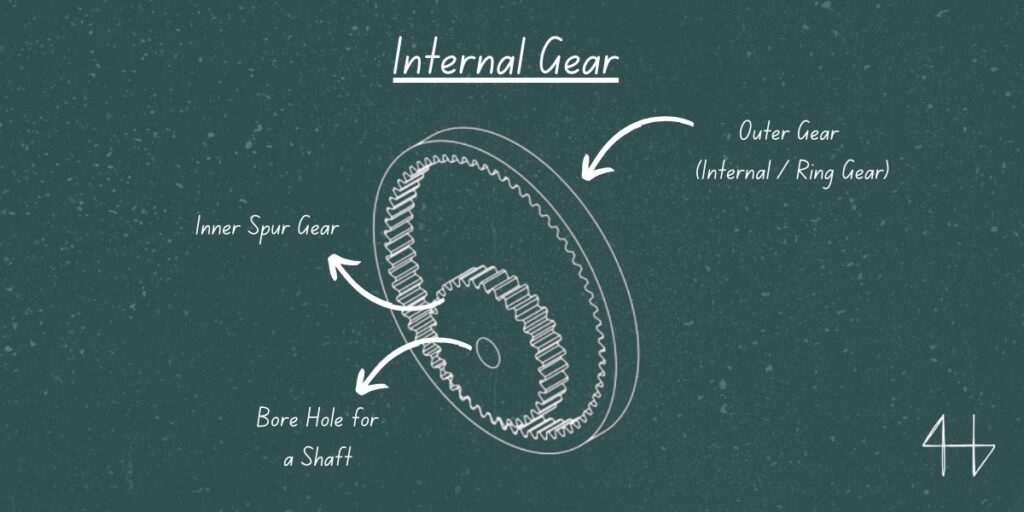
Internal gears have teeth on the inner surface and are often paired with external gears in planetary gear systems. They provide high torque in a compact form, making them essential in applications like automatic transmissions and differential systems.
Practical Application Examples
- 3D Printer direct drive extruders
- Automatic automotive transmissions
- Industrial gearboxes
Working Principle
The working principle of an internal gear relies on its teeth meshing with those of an external gear, often referred to as a pinion.
When the pinion rotates inside the internal gear, the teeth engage and transfer motion and power. Unlike traditional external gears, where the teeth are on the outside, internal gears create a smooth, compact design that allows for higher torque transmission in smaller spaces.
The interaction between the internal gear’s teeth and the pinion’s teeth ensures precise and efficient motion transfer, making it ideal for applications where space and power density are important.
Wrapping Up
In summary, understanding the different types of gear and their unique functions is essential for selecting the right gear system for any mechanical project.
Each gear type, from spur to helical to bevel, plays a specific role in controlling speed, torque, and direction of motion. With these insights, you can make more informed choices to optimize machinery performance and efficiency.
FAQs

What is the most common gear type?
The spur gear is the most common gear type, known for its simple design and efficiency in transmitting motion between parallel shafts.
What are the gear categories?
Gear categories include spur, helical, bevel, worm, and planetary gears, each designed for specific applications and motion requirements.
What is the most common steering gear?
The rack-and-pinion is the most common steering gear, widely used for its precision and ease of control in vehicles.
What are some mechanical alternatives for gears?
Mechanical alternatives to gears include belt and pulley systems, chain drives, and friction drives, which are used totransmit power in various machinery.

