Have you ever wondered what the most generic gear is called? Well, it’s called a spur gear. Trust me, there is more information to know about them than you would initially think.
But as simple as they are, spur gears can be overwhelming.
With so many technical details like the number of teeth, pressure angle, and materials like stainless steel & carbon steel it’s easy to get lost in the jargon. But mastering these essentials is key to designing machinery running smoothly, and efficiently, and hopefully doesn’t explode.
In this article we’ll break down the key parts of spur gears, and what really matters for your projects.
What is a spur gear?
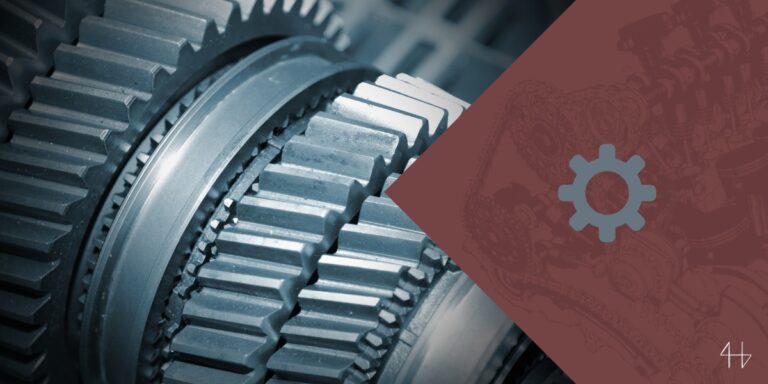
A spur gear is a cylindrical gear with straight teeth cut parallel to the axis of rotation, used to transmit power and motion between parallel shafts.
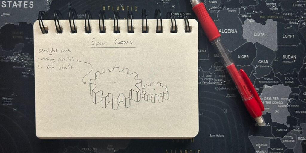
How to Identify spur gears?
Identifying spur gears involves several key dimensions and features.
First, check the pitch circle diameter (PCD)—this is the diameter where the teeth of two meshing gears engage and are critical for alignment.
Next measure the outside diameter—this is the total diameter across the teeth, which helps to distinguish between similar gears.
The center distance between two meshing spur gears is another critical factor, this is the sum of the pitch radii. Also, check the teeth alignment; in spur gears, the teeth are straight and parallel to the gear axis.
Basically, they should look something like this:
When to use spur gears
Spur gears are for when you need to transmit motion between two gears on parallel shafts.
They’re perfect for applications that require precise speed control and torque multiplication. Because of their simplicity, they’re good for low-speed applications where noise isn’t an issue. (They can be quite loud)
If you have machinery that requires a consistent diametral pitch spur gears will perform reliably.
Common applications are conveyor systems, automotive transmissions, and many manufacturing processes where power needs to be transferred smoothly and efficiently.
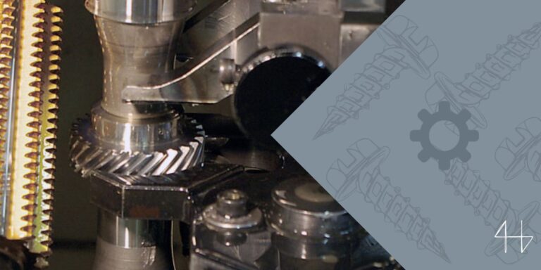
Spur gear manufacturing process
Spur gear manufacturing starts with material selection, where steel, brass, or plastics are chosen based on the gear’s application.
Once the material is selected the gear teeth are cut using specialized machines like gear hobbing or shaping machines which create the common involute tooth profile known for its ease of production.
After cutting the gears go through finishing processes like heat treatment or surface hardening to increase their durability and performance under load.
Finally, rigorous quality control to ensure the dimensional accuracy and tooth profile meets the required standard for the gear’s application so it runs reliably and efficiently.
Spur Gear Standards
Spur gears come in standard sizes that you can buy just about anywhere. Look them up when you are designing a mechanical system that needs spur gears.
If you really need a size of spur gear that is not a standard size, you can always find someone to custom-make it for you.
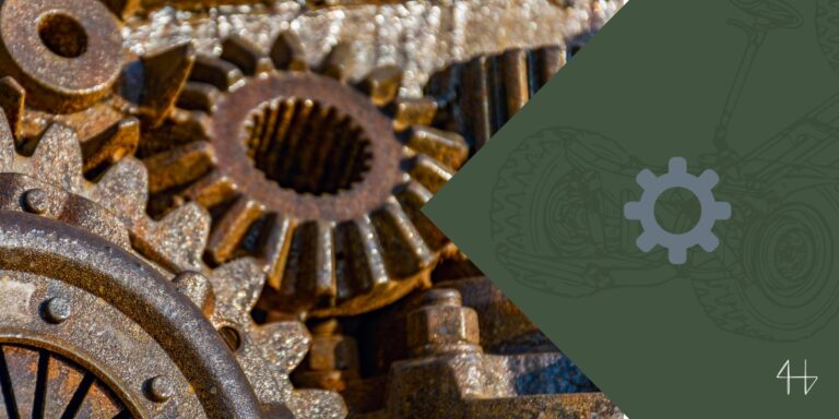
Applications of Spur Gears
Spur gears are regular components in the world of mechanical engineering.
Their simplicity and makes them a useful component that can easily be adapted for many applications. Here are some common areas where spur gears are used:
Power Transmission
Power transmission is the main function of spur gears so they are essential in many mechanical systems.
They transmit energy from one shaft to another by meshing their teeth which are parallel to the axis of rotation. This parallel alignment ensures smooth and reliable motion with minimal energy loss.
Spur gears are good for applications that require precise speed control and consistent torque, like:
- Automotive transmissions,
- Industrial machinery
- Conveyor belts
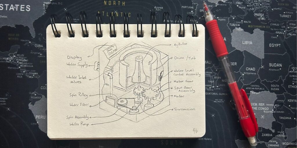
- Washing machines
They can handle heavy loads especially when heat treated for increased strength making them a go-to solution for durable and efficient power transmission.
Speed reduction and Torque Multiplication
Spur gears are used in speed reduction and torque multiplication applications where they adjust the speed and force within a mechanical system.
By pairing two gears with different numbers of teeth you can reduce the input speed and increase the output torque.
Or you could pair up a different gear to create speed-reduction assemblies.
This is useful in machinery where high torque is required to drive heavy loads but the input speed needs to be controlled
- Epicyclic gear trains to feed filament through a 3D printer
- Worm gear drives in elevators
- Cycloidal gears in robotics to ensure precision in movements
High-Speed Applications
Spur gears are typically used in low to moderate-speed applications due to their simplicity but can be used in high-speed applications when designed and manufactured with precision.
In these cases, material selection and heat treatment process are critical to increase the gears’ overall durability.
To manage the increased stress and noise at high speed these gears need careful attention to tooth profile accuracy and lubrication.
When optimized spur gears can transmit power in high-speed applications like
- Automotive engines,
- Turbines
- High-performance machinery where reliability and efficiency are key.
Spur gears Advantages and Disadvantages
Spur gears have many benefits but also some drawbacks. Their design and material properties affect their performance, especially in thermal expansion and overall efficiency.
You should know these factors when considering using spur gears in your design. Let’s break it down:
Advantages
Disadvantages
Limitations
These are the red flags you should know. The limitations are the deal breakers for design.
Trust me, you don’t want to end up redesigning a whole system because you thought that something “shouldn’t be a problem”
- Really noisy at high speeds. If you are looking for a quiet solution for your project, can I recommend a helical gear?
- The noise can cause vibration and wear. This will reduce the duration and life cycle of your project.
- High stress at heavy loads will cause premature failure.
- An incorrect number of teeth is unforgiving. This will cause interference between the teeth and lead to failure.
- Limited to transmit power between parallel shafts. So they are not suitable for applications where non-parallel shafts are required.
Conclusion
In summary, spur gears are essential components for their efficiency, simplicity, and cost-effectiveness.
They are good for applications where shafts are parallel and noise is not a problem.
By understanding their design features like pitch diameter and tooth surface and their limitations like thermal expansion and noise they can be effectively used in various mechanical systems.
Whether you are dealing with power transmission or speed control knowing when and how to use spur gears will improve your project’s performance and reliability.
FAQs
What is spur gear vs helical gear?
A spur gear has straight teeth parallel to the axis, it’s simple and efficient for power transmission between parallel shafts.
A helical gear has teeth cut at an angle to the axis, it’s smoother and quieter but more complex to manufacture.
What is the difference between traditional gear and spur gear?
The main difference between traditional gear and spur gear is the design.
Traditional gear including bevel or worm gear has angled teeth and can handle non-parallel shafts.
Spur gear has straight parallel teeth and is designed for parallel shaft arrangement, it’s simple and efficient for power transmission.
What is a spur gear?
Spur gear has straight parallel teeth that align with the gear axis, smooth and efficient power transmission.
Features: consistent pitch diameter, simple tooth profile, high load-carrying capacity.
Simple design and manufacturing, good for many mechanical applications.